Logic Trace System by The Logic Group

Logic Trace System by The Logic Group
The following steps usually fix the problem:
This works 99% of the time, if still having trobles, please contact us.
The Logic Trace Manual is a series of videos:
Logic Trace Software Installation (Windows)
Default Points/inch: The number of points per inch that will be saved in the file when using the Tracing or Curve Fit methods. The default is 20 points per inch. (The tracing board send 100 pts per second to the computer and the software changes this to so many points per inch).
Text File End of Line: Should be LF for Windows and CR for Apple Mac or Linux
Display Change Output Scale: When turned on program will prompt for a scale change when saving the file. Input change as a factor. EG 1.1 for 10% larger .9 for 10% smaller, 2 for 100% larger. However we recommend changing sizes on your CAD program, it will have more options.
Display Mirror Button: The mirror option only works on patterns created with the Tracing method. EG trace half a heart, click mirror.
Automatically save TLG file: The TLG file is the raw digitized data and the file is automatically created whenever you save a file. The TLG file can be loaded by clicking the Options Button and then the Open TLG File Button.
Below are the instructions for setting and changing the Calcomp Drawingboard VI settings. Changing them is VERY UNCOMMON and we recommend only changing them if requested by us.
This is almost always caused by a unit conversion problem. The Logic Trace software is outputting the pattern in inches in the DXF file and the CNC software is reading the file as millimeters causing the pattern to be significantly smaller. There are three different solutions to this problem: Before loading the DXF file into your CNC software make sure the CNC software is going to read the file in inches. Change the Logic Trace software to output the file in millimeters. At the top menu click Setup - Units, scale units to cm/cm, and DXF file units to mm. In the Logic Trace software change the scale to 25.4 which will increase the size of the file. On the left menu click the scale button, input scale keyboard, input 25.4 for the scale and then click Done You only have to do one of the 3 solutions.
The digitizing boards can be effected by electrical and magnetic interference. If you sometimes don't get a point, hear beeps when not digitizing, get extra lines, or strange circles, or not the desired accuracy we need to check for interference.
The pen stylus and cursor generate a magnetic field that is "sensed" by the electrical grid in the board. Magnets can interfere with the board. Make sure no magnets or electrical devices with magnets are near the board. Laptops, computers, and cell phones have magnets and should be a few inches away. If you want to sit a computer on the board have it a few inches above like on a thick yellow pages directory from the old days.
Overhead florescent lights can generate a problem that interferes with the board. If having problems try turning off the overhead lights. If this is the problem replacing the overhead florescent bulbs with LED bulbs will fix the problem.
Power supplies and power strips can generate a weak electro-magnetic interference. If you the digitizers with a power supply make sure the surge protector and power adapter are on the floor a few feet away. Make sure the power outlet is properly grounded.
Very rare but the digitizing can be interfered with some metallic inks printed on paper or inks in plastic.
Corded pens and cursors have less interference issues than cordless ones. I would be happy to send you a corded pen or cursor to try if you want.
See the next section on interference caused by metals.
The digitizing can be affected by some metals which interferes with the magnetic field from the pen or cursor. The amount of interference depends on the type of the metal and the thickness. For most metals the board does just fine with the outside of the part, it is the inside holes that are having troubles.
In this case put a piece of paper down on the board, put the part on top of the paper, digitize the outside of the part, draw the inside holes on to the paper, lift the part off the paper and digitize the holes drawn on the paper. Occassionally the outside of the part may need to be also traced on the paper.
At Home Depot in the paint department they sell rolls of brown paper for protecting floors from paint drops. That paper changes color when wet. Some people will put that paper down, put the part on top, use a spray misting bottle to spray water in the holes, and then lift the part and digitized the water stains.
Steel and stainless steel have minimal interference, they just have problems with the holes. Aluminum causes the most interference. When tracing aluminum you may need to trace both the outside outline and inside holes onto the paper.
Over half of my clients are metal fabrication shops and they find that in most metal tracing jobs the interference is minimal.
There is only one pen stylus. The tracing board has an electrical grid underneath the surface - a bunch of wires going up and down and across. The pen stylus generates a magnetic field. Get the pen stylus close to the board and the board senses the magnetic field and knows exactly where the tip of the pen is. The pen does not need to be touching the board. Push a button on the pen and points go to the computer which the logic trace software turns into a DXF file.
Usually most people have no troubles tracing the outside of parts with the pen stylus it is the inside holes that cause issues. There is an easy fix. At the hardware store in the paint department they sell brown paper for protecting floors when painting. That paper changes color when wet. Try placing the paper on the board, place the part on top of the paper, trace the outside of the part, with a misting bottle spray water droplets in the inside holes, lift the part up, and then trace the wet spots.
If the template is nonmetal for example a cardboard template, some people will trace the top of the template using the pen stylus or the cursor.
To join one or more open paths, use the Selection tool to select the open paths and click Object > Path > Join. You can also use the keyboard shortcut Ctrl+J (Windows) or Cmd+J (Mac). When anchor points are not overlapping, Illustrator adds a line segment to bridge the paths to join.
Check B-10 Setting B-10 on the digitizer turns the digitizer beep on and off. If B-10 is on the digitizer will beep and if B-10 is off no beep. To change the setting using the pen or cursor, digitize/click the Config/Exit button on the digitizer in the lower left hand corner. The digitizer will beep twice. Digitize/click the Bank B button. The light on the upper right corner should be ON. Move the pen to the 10 box. Place the tip of the pen on the 10 box but do not digitize/click the box. If the light in the corner is ON the beep setting is ON. If the light in the corner is OFF the beep setting is OFF. To change, digitize the 10 box with the pen. Digitize the Save Default button, the digitizer will beep twice. Digitize the Config/Exit Button the digitizer will beep twice.
Check B-14 Setting Setting B-14 on the digitizer should be on. This setting increases the digitizer accuracy when using the pen stylus by performing a pen angle correction. Boards usually ship from the manufacturer with this setting on.
Using the pen or cursor, digitize/click the Config/Exit button on the digitizer in the lower left hand corner. The digitizer will beep twice. Digitize/click the Bank B button. The light on the upper right corner should be ON. Move the pen to the 14 box. Place the tip of the pen on the 14 box but do not digitize/click the box. The light in the corner should be ON. If it is not, digitize the 14 box and the light will come on. Digitize the Save Default button, the digitizer will beep twice. Digitize the Config/Exit Button the digitizer will beep twice.
Click the "Can't Digitize" button on the lower left part of the Logic Trace software screen. This will reset the Tabletworks driver and restart the Logic Trace software. Try again to digitize. If this doesn't work try the following (Plan A or Plan B work 99% of the time):
Plan A Instructions Try First
1. Exit Logic Trace 2. Start tabletworks 3. Click Remove Tablet, if more than one remove all of them 4. Make sure digitizer is turned on 5. Click refresh List, did it find it? 6. Click Wintab at top, click Apply at bottom, Click Close 7. Start Logic Trace, digitize new 8. Top menu choose Setup, tablet setup 9. Choose Wintab Any Manufacturer, size, click install 10. Click Test XY, digitize a point 11. Should get X=xxxx, Y=yyyy
Plan B Instructions If A Doesn't work
1. Take the usb cable out of the computer 2. Start Tabletworks and click remove tablet on right to remove all tablets 3. Reboot the computer 4. Start tabletworks 5. Reattach the usb cable (works better if you reattach to a DIFFERENT usb port) 6. did Tabletworks find the digitizer, if not make sure it is turned on and click refresh list 7. Click Wintab at top, click Apply at bottom, Click Close 8. Start Logic Trace, digitize new 9. Top menu choose Setup, tablet setup 10. Choose Wintab Any Manufacturer, size, click install 11.. Click Test XY, digitize a point 12. Should get X=xxxx, Y=yyyy
Plan C Instructions If A and B Doesn't work
If that doesn't work, more complete reset is needed 1. unattached the digitizer usb from computer 2. uninstall Tabletworks 3. reboot computer 4. re-install Tabletworks 5. reboot computer 6. reattach usb to computer 7. check wintab in Tabletworks and apply, ok 8. test xy in logic trace
If still having problems call 512-656-8195 or email [email protected]
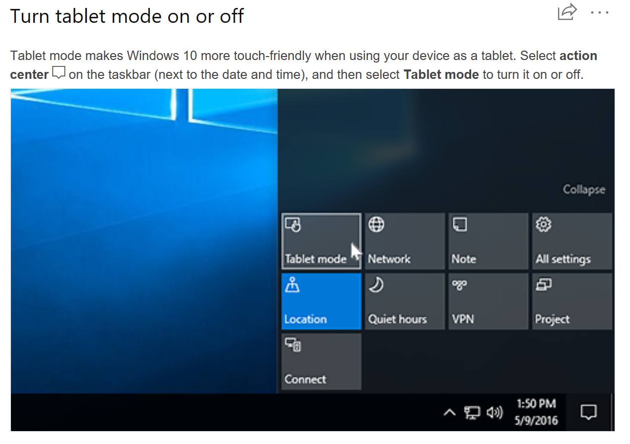
The Logic Trace software requires the computer to have the Tablet Mode turned OFF in Windows 10.
The Logic Trace Manual is a series of youtube videos:
1. Installing the driver, software, digitizer, testing:
https://logicgroup.vids.io/videos/4d9dd7b91c18e6c2c4/2018-logic-trace-installation
2. Two digitizing examples
https://logicgroup.vids.io/videos/449dd7b91c18e6cfcd/two-digitizing-examples
3. Demonstrating different methods of digitizing
https://logicgroup.vids.io/videos/069dd9bb141ce6c58f/to-demonstrate-different-tracing-selections
4. Digitizing smooth curves using Spline curve fit
https://logicgroup.vids.io/videos/119dd7b91c18e7cf98/spline-curve-fit-example-guitar
5. Lines and Arcs Example
https://logicgroup.vids.io/videos/ac9dd8b41d19e6c525/a-good-example-of-lines-and-arc-selection
6. Spline curve fit example
https://logicgroup.vids.io/videos/d39dd8b41d19e7c75a/curve-fit-through-points
7. Software Compatibility
We have additional videos on our video library
If you are having troubles downloading the Logic Trace software, try the following::
1. If using Microsoft Edge, click "keep" or "install anyway" if asked. You may need to click three dots (...)
2. Try using a different browser to download the software.
3. Some people have to download the software on another computer, save to a USB drive, and then install on a different computer using the USB drive.
4. Occasionally an antivirus program will delete the file after it has been downloaded but before the software is installed. You may need to turn your antivirus program off for five minutes while you download and install the software.
I can always send you a CD to install from a CD. This is quite unusual almost everybody is able to use the steps above to download and install the software.